Assembly instructions
0. Get ready
Parts Included:
- PCB, top-plate, bottom-plate (comes as one piece, with perforated tabs to split apart)
- Pro Micro controller. Kailey has pre-flashed them for Windows.
- 4 switches
- 4 keycaps
- 1 reset button
- 4-6 M2 spacers
- 8-12 M2 screws
- 4 bumpons
Tools required:
- safety first: eye protection
- soldering iron
- solder (very little needed on a board this size)
- phillips screwdriver
- little snips/flush cutters
- helpful: scotch tape, rubberband or breadboard (see optional below)
- helpful: small flathead screwdriver or switch puller (see optional below)
Optional:
- Sandpaper or some other method of smoothing out the edges after snapping it apart.
- Breadboard (very common in DIY electronics kits)
- Switch puller
- Super glue
1. Break apart the PCB and plates.
I'll refer to the sections as "top plate" (with large holes), "bottom plate" (opposite piece, quite boring), and "PCB" (the smallest/middle section)
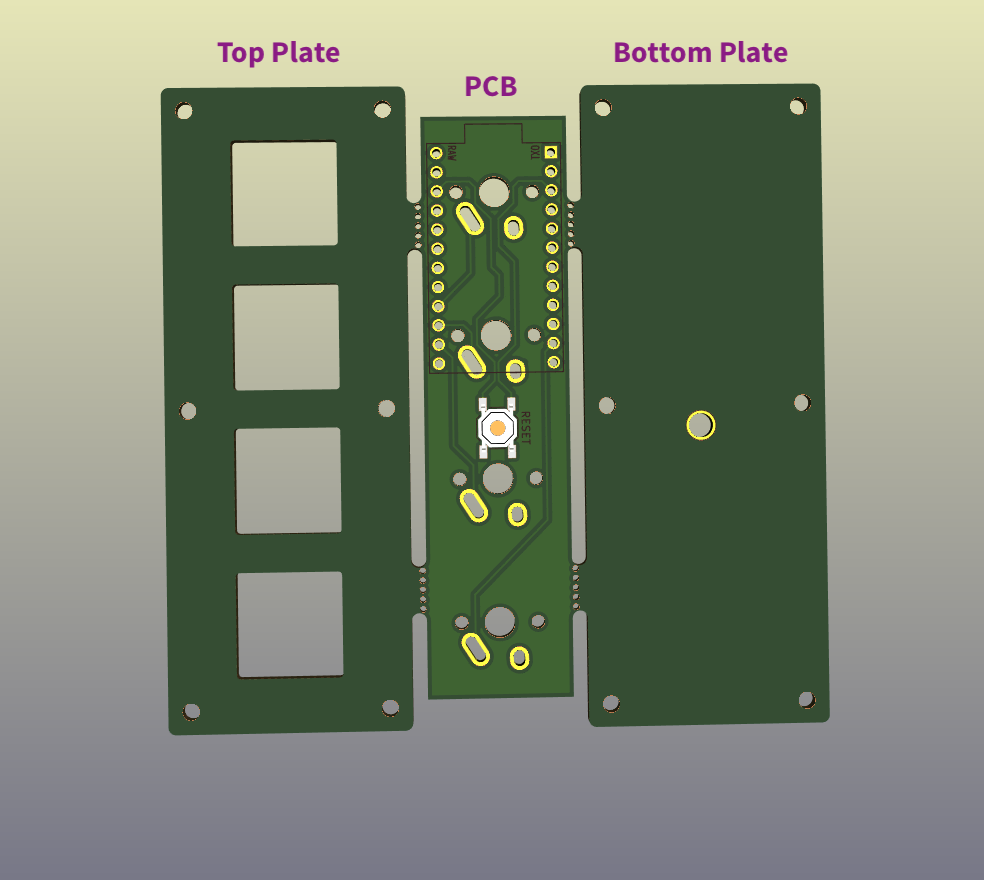
I recommend starting by separating the bottom plate. Because it's solid, it'll give a better feel for the pressure required and help to reduce risk of breaking the top plate. I haven't broken any yet, so maybe they're tougher than I expect.
At this early stage, I'll also suggest putting a teeny spot of super glue on the Pro Micro between the USB port and the board. Once in a while this area is a little weak. I've never had one fully break, but a little extra support here doesn't hurt. Replacing a broken Pro Micro after it's been soldered in is possible, but not fun.
2. Solder in the reset switch.
This step can happen later, but it's easiest now while the board is clear.
This is an SMD (surface mount device; e.g. doesn't go through a hole on the board) which can take a little finesse. Usually some tweezers or even a bit of tape to help hold the component in place while the leg is soldered is helpful
There is no polarity, so it doesn't matter which way (as long as it fits).
This is a convenience component, if something goes terribly wrong, the rest of the board should be okay. In fact the reset button isn't needed until you decide to customize the functionality, which isn't part of this guide.
3. Solder in the Pro Micro pins.
❗️Steps 3, 4, 5 must happen in order, or else you may block access to the areas that need to be soldered. Desoldering is possible, but frustrating, avoid if possible :)
- Approach #1: Solder in all the pins. This is tedious, but covers all the bases.
- Approach #2: Solder in only the needed pins (plus corners for stability). The keyboard design only depends on 6 pins of the Pro Micro, so we can minimize the amount of soldering required, but must make sure all the right pins are soldered.
- Approach #3: The middle ground... All of our necessary pins are within 4 spaces of a corner.
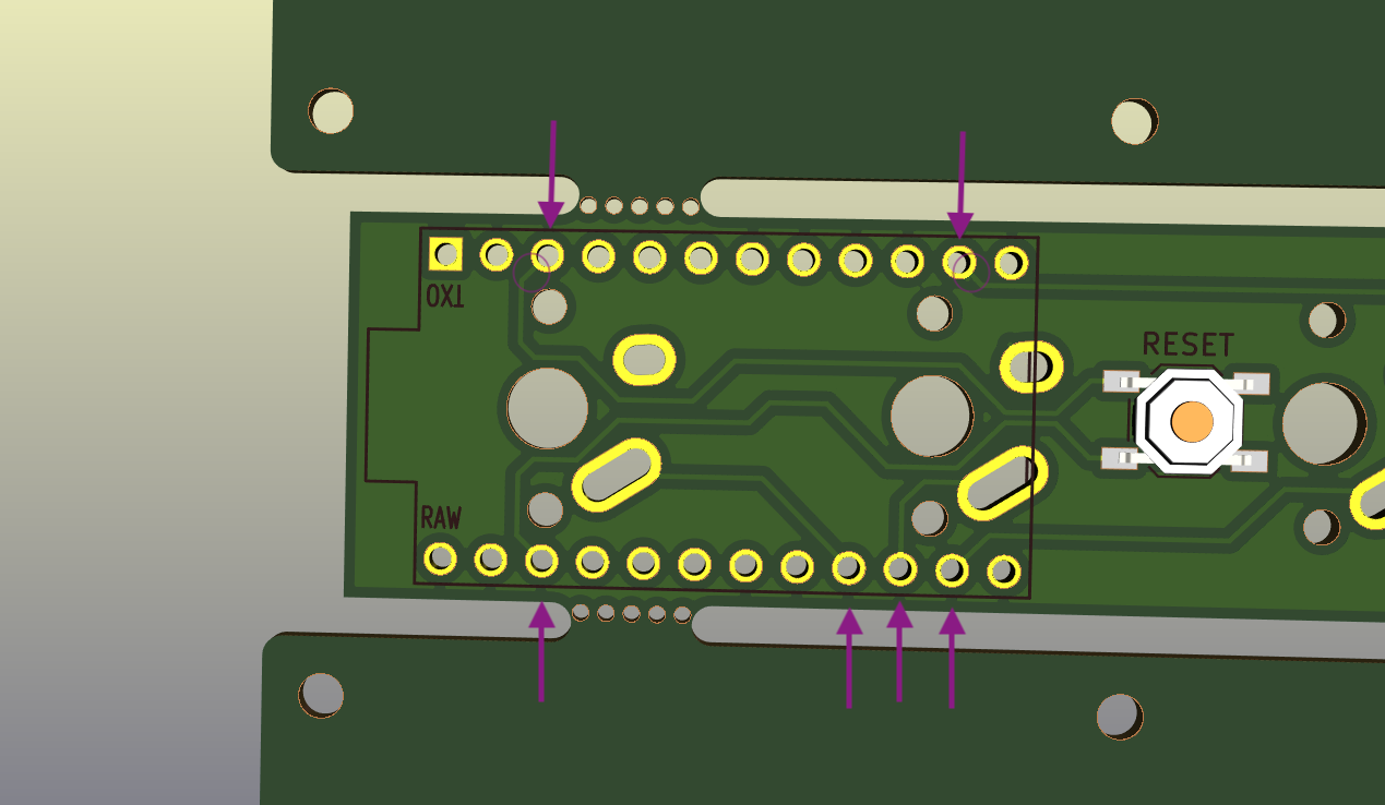
Picture shows the must-haves, marked with arrows. If you follow the lines on the board, they lead to these 6 locations (2 are lightly circled). Don't forget corners for stability.
With the reset switch facing up, place the pins into the board, short-side in.
These will be wobbly, and we need to solder the back side of the PCB, so we need a way to keep them stable and straight.
- If you have an electronics breadboard: you can carefully place the pins there, set the PCB on top, shim something in there to keep the PCB from tipping, and solder.
- Otherwise, you can place the Pro Micro in the pins (DO NOT SOLDER THIS YET), use a little tape or rubberband to keep it steady and solder the back side.
4. Solder in the switches
Remove the Pro Micro if you used that in the last step.
Insert the switches into the top plate.
Check all the switch pins are straight. It is not uncommon for these to get flattened, but they can be bent back into position.
Place the top plate with switches on to the PCB.
Check bottom side that the pins are all coming through so they can be soldered. If any are bent, they need to be fixed before soldering starts, or else you won't be able to reach them very well.
Solder in the switch pins. These are large holes and don't need to be fully filled with solder. Just ensure a solid connection between pins and the PCB.
⚠️ Safety glasses.
For the 2 switches/4 pins near the Pro Micro pins, trim the excess pin sticking out. This will ensure the Pro Micro fits nicely and doesn't get shorted out.
Touch up the solder near snipped pins, as the trimming can weaken the bond.
5. Solder in the Pro Micro
Now lay the Pro Micro onto the pins. Flat side facing up so that the USB port will fit snuggly against the top plate.
Solder the pins.
⚠️ Safety glasses.
Trim the excess length. These pins are thicker, so watch out.
Again, touch up the solder to make sure the bond stays strong.
6. Assemble the case
There are screw holes on the sides, but these are not used. In this version of the PCB, I did not leave enough space for the standoffs/spacers.
I recommend starting by near the USB end, but it's up to you. Note, there is zero extra space for the spacers, they will rub up against the PCB, but it should not be a forced fit.